Key Takeaways
A more flexible 6G synchronization signal structure is under study. The 3GPP Radio Access Network Working Group 1 (RAN1) discussed draft terminology that would replace 5G’s fixed structure of up to 64 Synchronization Signal Blocks (SSBs) per burst with a more flexible “6G Radio (6GR) SSB burst” and “6GR SSB burst set.”
The study framework for 6G Physical Random Access Channel (PRACH) design was agreed. RAN1 agreed to study base sequences and preamble generation methods for 6G PRACH, benchmarked against the 5G New Radio (NR) Zadoff-Chu (ZC) design. Agreed evaluation targets are 0.1% false alarm and 1% miss detection. ZC sequence may be a preferred sequence from a majority of companies, but candidate families under study include extended ZC, polynomial-phase designs, multi-root designs, and preamble aggregation.
The Random Access Channel (RACH) procedure direction is to simplify, not add more special cases. Simplification of preamble formats compared to NR PRACH preamble formats is generally desired. A widely-supported direction — reinforced by a liaison from the 3GPP Radio Access Network Working Group 2 (RAN2) — is to minimize excessive PRACH partitioning and prefer Msg3 for conveying User Equipment (UE) capability information.
Overview
The April 2026 RAN1 interim meeting (RAN1 #124-bis) ran April 13–17, 2026, in St. Julian’s, Malta, alongside the other RAN working group meetings that week. It was the first RAN1 session after the March plenary in Fukuoka, where the fundamental channel bandwidth framework for 6G was settled. The Release 20 study on 6GR is now roughly one-third of the way through its study phase.
RAN1 addressed many agenda items at Malta across the 6GR study and ongoing 5G work. This readout focuses on one of them: initial access. Before a phone, laptop, or any wireless device can send or receive a single byte of user data, it has to find a base station, time-align with it, and establish a connection. That process — everything from the device first listening for a signal to the base station acknowledging it — is called initial access. In 5G today, initial access typically takes tens to hundreds of milliseconds, and it may happen every time a device wakes from deep sleep, moves between cells, or powers on. Because it happens so often and consumes energy on both sides, the design of these first few milliseconds has an outsized effect on battery life, coverage, and how quickly the network responds when a device is trying to get back on the air.
Designing the 6G Initial Access Procedure
In 6G, initial access becomes more challenging than in the 5G NR design. 6G is expected to support wider bandwidths, around-7 GHz deployments, integration between Terrestrial Network (TN) and Non-Terrestrial Network (NTN) operation, multi-carrier and multi-Transmission/Reception Point (multi-TRP) operation, diverse UE types, and stronger coverage and energy-efficiency requirements. The initial access design therefore cannot simply copy NR — it must be scalable enough for high-performance enhanced Mobile Broadband (eMBB) UEs while still supporting low-tier or bandwidth-limited devices, and it must maintain acceptable access delay, detection reliability, coverage, and UE complexity. 6G will also lean more heavily on network and UE energy saving techniques such as longer sync-signal periodicity, on-demand SSB and System Information Block 1 (SIB1) transmissions, and wake-up signaling, each of which can reduce always-on network transmissions but may also increase cell-search latency, paging delay, or mobility-measurement delay if not carefully designed.
Every cellular connection starts the same way. The device powers on, listens for a synchronization signal from a nearby base station, decodes some basic configuration, and then transmits a short preamble to announce itself. Only after that handshake completes can any real data flow. 6G inherits that overall shape from 5G NR, but the specific signals, sequences, and procedures inside it are being reworked.
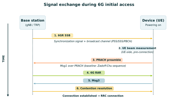
Figure 1: Signal exchange during 6G initial access. The six-step sequence follows the established NR-style random access flow; 6G inherits the overall shape but individual signals, sequences, and procedures inside it are under study.
Sync Signals and a Flexible SSB Structure
The first step in NR access is cell search. A UE scans for synchronization signals carried in SS/PBCH blocks, often called SSBs, transmitted by the gNB. Each SS/PBCH block contains PSS, SSS, PBCH, and PBCH DM-RS. Together, these let the UE acquire time and frequency synchronization, determine the physical cell ID, and decode the MIB needed to obtain system information block. In 5G NR, candidate SS/PBCH block locations are defined within a 5 ms half-frame, and the number of candidates depends on the number of transmission beams, subcarrier spacing and frequency range; the maximum can be 64. In beam-swept deployments, different SS/PBCH block indexes are commonly associated with different beams, although the standard specifies SS/PBCH block indexes rather than a mandatory unique beam index. That design works, but it constrains the network in two ways that matter for 6G.
First, the initial-access SSB is a cell-common signal, rather than a UE-specific signal. Before a UE is connected, the network cannot target synchronization information to that UE individually, so in beam-based deployments the cell exposes coverage by transmitting a configured set of SS/PBCH block positions, often mapped by implementation to different transmit beams. NR allows up to 64 candidate SS/PBCH block positions in a 5 ms half-frame for certain configurations. Still, when a high-frequency cell transmits many SSBs to remain discoverable at UEs, those transmissions consume downlink resources and RF energy even when no UE is trying to access the cell in a given direction.
That standing energy cost exists whether the cell is busy or idle, and it grows as beam counts grow — a concern at the 7 GHz frequencies 6G is targeting, where narrower beams and more of them are needed to close the link budget.
Second, the 5G SSB structure assumes operation per individual cell. A “cell” in cellular networking is the coverage area served by one logical transmitter with one cell identity, which the device learns from the SSB. Modern deployments increasingly involve multiple TRPs — distributed antennas, remote radio heads, or small cells — cooperating to serve one area. Under the 5G design, each TRP either needs its own cell identity and its own SSB stream, or all TRPs must transmit the same SSB and the device cannot tell them apart. Neither fits multi-TRP operation cleanly.
At the Malta meeting, RAN1 worked with new draft terminology meant to open up both constraints. A proposed 6GR SSB burst is one or more SSBs transmitted together, and a proposed 6GR SSB burst set is one or more of those bursts combined. The terminology is explicitly for discussion purposes and has not been formally adopted. The flexibility it describes is deliberate: the same physical SSB could be repeated within a burst for coverage enhancement, and multiple bursts could be combined into a burst set to support transmission patterns. Simulation analysis presented in the discussion showed that clustered SSB concept with a longer periodicity than 20 ms SSB periodicity could bring base station power consumption down to roughly the level of 5G NR at 4 GHz.
A separate but closely related question concerns the bandwidth of the SSB and other common initial-access signals/channels. At RAN#110, the plenary confirmed that 6GR supports operation in a minimum spectrum allocation of 3 MHz with 15 kHz SCS, while also clarifying that this minimum-allocation case is not required to be optimized for performance. This creates an important design constraint: 6GR must be able to operate in very narrow spectrum, but the air-interface design does not necessarily have to make the 3 MHz case the main performance-optimized design.
The practical reason is straightforward. Some deployments may be constrained by fragmented or narrow spectrum allocations, and some lower-tier device classes may be expected to operate with much smaller bandwidth than high-end devices. A 6GR design that cannot support 3 MHz operation would be difficult to use in those narrow-spectrum cases. At the same time, forcing all common initial-access signals/channels to be designed natively around 3 MHz could overly constrain the design for wider deployments. This is why the issue is not simply “make SSB fit in 3 MHz,” but rather how to support 3 MHz operation while preserving a robust and scalable initial-access design.
Two approaches are captured in the agreements. Option 1 is to design the common initial-access signals/channels, at least including SSB, by assuming a bandwidth larger than 3 MHz. With the RAN#110 clarification, this bandwidth is assumed to be at least 5 MHz with 15 kHz SCS. The resulting design would then be made applicable to any spectrum allocation, including 3 MHz, with adjustment if needed. Option 2is to define a single common initial-access design by assuming the 3 MHz minimum spectrum allocationas the target bandwidth, and to apply that design to any spectrum allocation.
The trade-off is clear. Option 1 gives the SSB/common-channel designer more bandwidth to preserve synchronization, PBCH, and common-channel robustness in normal deployments, but it requires a well-defined adjustment mechanism for the 3 MHz case. Option 2 is cleaner for the minimum-allocation case, because the design is natively built around 3 MHz, but it may impose a narrower design on wider deployments and could limit performance or design flexibility. Therefore, the key question is whether 6GR should use a more capable common initial-access design, with adaptation for 3 MHz, or whether it should make 3 MHz the native target for the common initial-access design.
Preamble Sequences and the RACH Procedure
Once a device has synchronized with the cell, the first uplink step is to transmit a random access preamble through the PRACH. The PRACH is the “raise your hand” channel — a dedicated uplink resource that a device transmits on when it has no existing connection and needs uplink timing alignment and network attention before it has normal uplink resources. The short waveform it transmits is called a preamble. In NR, the PRACH preamble design is based on ZC root sequences, with individual preambles generated through cyclic shifts of a root sequence. This remains the reference baseline for 6GR evaluation — not because RAN1 has decided to freeze the NR design, but because ZC provides a mature benchmark with well-understood correlation, timing-estimation, and low Peak-to-Average Power Ratio (PAPR) properties. The 6GR question is whether that baseline remains sufficient under the new random-access targets: improved coverage, energy-efficient access, diverse device types, higher capacity, high-speed mobility, and operation under NTN, Subband Full Duplex (SBFD), multi-carrier, and multi-TRP assumptions.
At the Malta meeting, RAN1 agreed to study base sequences and preamble sequence generation/construction methods for 6GR PRACH. The study will consider detection performance — including timing-advance estimation, frequency-offset handling, miss detection, false alarm, false detection, and auto- and cross-correlation — along with base-station detection complexity, UE implementation complexity, cubic metric/PAPR, supported sequence lengths and associated SCS, preambles per RACH Occasion (RO), inter-cell interference, and coexistence with 5G NR PRACH. Candidate designs are expected to be benchmarked against NR PRACH rather than judged on any single metric such as sequence-pool size or PAPR alone.
Several companies brought candidate directions during the week. Some proposals favored reusing or extending the NR ZC-based design; others proposed enhanced constructions such as extended ZC, polynomial-phase designs, multi-root designs (e.g., concatenation of two ZC root sequences, bi-rooted preambles), and preamble aggregation. Polynomial-phase designs are best characterized as one candidate family — reported benefits included lower PAPR variation and a larger candidate sequence pool, but those gains still need to be validated under the agreed RAN1 evaluation framework.
RAN1 also aligned the evaluation methodology. Miss detection covers both failures to detect the transmitted target preamble and correct preamble detection with wrong timing estimation; an extended metric also considers wrong frequency estimation. False alarm is defined as detecting a target preamble when no transmission occurred, with additional metrics covering intra-cell false detection, inter-cell false detection, and mixed false detection. For PRACH evaluations, the agreed targets are 0.1% false alarm and 1% miss detection, with companies reporting detailed sequence and format assumptions. The agreed RO assumptions are 32, 64, and 128 preambles per RO — with other values up to companies to report — and 1, 2, 4, and 8 UEs per RO.
On preamble formats, the direction is study-oriented rather than solution-oriented. RAN1 agreed to identify the deployment characteristics that should drive 6GR RACH preamble format design, including target Round Trip Time (RTT) or maximum cell radius, target preamble duration, target Doppler and UE mobility, duplex scheme, PRACH SCS, and operating frequency range. A clear observation was that simplification compared with NR PRACH preamble formats is generally desired. This means 6GR should avoid accumulating more special-case formats unless a specific coverage, mobility, NTN, SBFD, or frequency-range requirement justifies them.
The RACH procedure discussion similarly points toward avoiding the fragmentation seen in later NR releases. The random access procedure in 5G uses a sequence of messages — Msg1 (the preamble itself), Msg2 (the network’s random-access response), Msg3 (the first uplink data transmission carrying UE identity and capability information), and Msg4 (contention resolution). 4-step RACH keeps these as distinct steps; 2-step RACH collapses Msg1 and Msg3 into a single transmission called MsgA. At Malta, 4-step RACH remained the robust baseline in most company views, while 2-step RACH / MsgA evaluation parameters were agreed for further study. The broader theme is to design coverage, capacity, and energy-saving features from Day 1 rather than layering them release by release. A related, widely-supported direction from multiple companies — and reinforced by a liaison from RAN2 referenced in the feature lead summary — is to minimize excessive PRACH partitioning and prefer Msg3 for conveying UE capability information, on the grounds that excessive Msg1 partitioning reduces effective preamble resources and increases configuration complexity. RAN1 is studying identification of the essential information that should be conveyed via Msg1 versus Msg3; this work continues.
What’s Next
Before the next major plenary, RAN1 will hold one more working group meeting (RAN1 #125) in May 2026 where the topic-level work from Malta continues. The next major milestone after that is the RAN plenary in June 2026, which will take interim decisions on fundamental 6G parameters including waveform, channel bandwidth, frame structure, numerology, and synchronization signal structure. The work done at Malta on initial access feeds directly into both.
Companies will bring concrete PRACH sequence candidates for evaluation — benchmarked against NR PRACH under the agreed RAN1 evaluation framework (0.1% false alarm / 1% miss detection, sequence and format assumptions). Discussion on the 6GR SSB burst and burst set terminology continues. On RACH procedure, identification of essential information to be reported by Msg1 versus Msg3 remains future work.