


Key Takeaways
- RAN1 kept the 5G control channel structure for 6G and lifted the MIMO ceiling to 48 demodulation reference signal ports. Existing control channel receivers remain a valid starting point, while the data channels get twice 5G’s ports and 8, 12 or 16 layers per device to choose from. RAN1 also answered the plenary’s checkpoint questions, finding no consensus on constellation shaping, which ends that study under the plenary’s rule, concluding that the highest-order QAM, if supported, is limited to fixed wireless access, and keeping the 5G width of the synchronization signal block.
- RAN2 ended the study of connected-mode mobility without network notification and moved toward merging 5G’s duplicate procedures. Most of the 5G Layer 2 design carries over, while the group left open the baseline for aggregating radios on different sites over a slow backhaul.
- SA2 consolidated about two dozen proposals into three candidate architecture options differing in how AI is supported in the 6G system and kept the 5G interworking path open. Solutions for moving devices between 6G and the 5G or 4G cores were updated and approved, but whether 6G mobility management evolves from the 5G access and mobility management function remains open.
Overview
Many of the chips and base stations that carry 6G will also carry 5G, so every part of the 5G design that 6G keeps saves cost and risk, and every part it replaces has to justify the change. In late August 2026, RAN1 and RAN2 met in Maastricht for RAN1#126 and RAN2#135, and SA2 met in Prague for SA2#176. Each firmed up answers in its own area, whether the radio signals, the procedures a device follows, or the core network behind the radio. The RAN plenary’s decisions in Madrid two weeks later are covered in a companion readout.
RAN1 keeps the 5G control channel structure and doubles the DMRS port count
RAN1 designs the radio signals themselves, and Maastricht was also a checkpoint meeting at which the RAN plenary expected firm answers on modulation, channel coding and the synchronization signal. On the control channel, it agreed that a 6G control channel element (CCE) consists of 6 resource element groups (REGs) and that at least aggregation levels 1, 2, 4, 8 and 16 are supported, the same set 5G uses to trade capacity for robustness. Control resources can be allocated contiguously or non-contiguously in frequency, in units of 6 resource blocks as in 5G with other granularities still under study, which helps when 6G shares spectrum with 5G. For that sharing case, known as multi-RAT spectrum sharing (MRSS), RAN1 agreed that the resource block grids of 5G and 6G line up on the shared carrier, and after the meeting it sent the plenary a preliminary assessment of MRSS performance. RAN1 also settled how uplink control information is carried. 6G will have a dedicated uplink control channel and will also carry that information on the uplink data channel, with the ambition of getting by with two or three formats instead of 5G’s five. Taken together, existing control channel receiver designs remain a valid starting point for 6G.
Up to 48 DMRS ports for the 6G data channels
On the physical downlink shared channel, a base station can send several spatial layers at once, to one device (single-user MIMO) or to several devices on the same resources (multi-user MIMO). Each layer is demodulated using its own demodulation reference signal (DMRS) port, the known pilot pattern a receiver uses to estimate the channel, so the number of orthogonal ports is the ceiling on how many layers can be scheduled together. Ports are kept apart in three ways. They are placed on different sets of subcarriers, called code division multiplexing (CDM) groups, and separated within a group by a frequency-domain orthogonal cover code. When DMRS occupies two consecutive symbols, a time-domain orthogonal cover code (TD-OCC) of length 2 doubles the count. 5G reached 24 ports in Release 18 and supports up to 8 downlink layers for one device.
In Maastricht RAN1 raised the ceiling to 48 orthogonal DMRS ports with a TD-OCC of length 2, while the maximum for single-symbol DMRS is for further study and capped at 24. The same limits were agreed for the uplink data channel, at least when it uses the CP-OFDM waveform. RAN1 narrowed the design candidates to comb-based CDM groups, cover code lengths of 2, 4, 8 or 12 in frequency and 1 or 2 in time, and 2, 3, 4, 6 or 12 CDM groups. The DMRS sequence stays a Gold sequence initialized from a scrambling identity or the physical cell identity, as in 5G. The per-device limits also changed: the maximum number of layers per device will be selected from 8, 12 or 16, shortlists were agreed for how codewords map onto layers, and a device can be told about co-scheduled users so it can suppress their interference. Because every resource element carrying a pilot is unavailable for data, more ports also mean more overhead, and RAN1 will study two ways to reduce it, sparse orthogonal DMRS and superimposed pilots, and strive to select at most one. That choice, like the layer count and codeword mapping, will be decided by simulation results at the next two meetings.
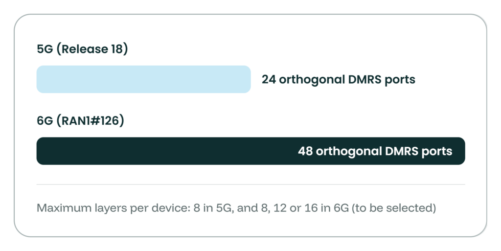
Figure 1. RAN1#126 set the maximum number of orthogonal DMRS ports for the 6G downlink and CP-OFDM uplink data channels at 48, twice the 5G Release 18 ceiling.
Plenary checkpoints: constellation shaping, high-order QAM, LDPC BG3 and the SSB
The RAN plenary had set the third quarter of 2026 as the deadline for several open questions, and RAN1 answered them in Maastricht. The most visible concerned constellation shaping, which changes either the spacing of the points in a QAM constellation (geometric shaping) or how often each point is used (probabilistic shaping) so that the transmitted signal comes closer to the theoretical capacity of the channel. Supporters of shaping split between a geometric scheme and several probabilistic variants, while more than twenty companies opposed shaping altogether. RAN1 concluded that there is no consensus to support any constellation shaping scheme for either the downlink or the uplink, and under the plenary’s rule that ends the study.
Higher-order modulation was settled on similar ground. 5G tops out at 1024-QAM in the downlink and 256-QAM in the uplink. If 6G supports 4096-QAM in the downlink or 1024-QAM in the uplink, it will be only for fixed wireless access, where a stationary customer premises unit with a good line of sight can sustain the signal quality those dense constellations need, and not for mobile broadband. The restriction is to be enforced in the specification rather than left to deployment choices. Within that scope RAN1 recommends adopting 1024-QAM for the uplink, but found no consensus to recommend 4096-QAM for the downlink.
Channel coding produced a capability decision. 6G is designing a new low-density parity-check (LDPC) base graph, BG3, alongside the two base graphs 5G uses for its data channels. RAN1 agreed that uplink support for BG3 is mandatory, with capability signaling, for every device except those whose maximum uplink channel bandwidth does not exceed 20 MHz in any band they support, for which it is optional. Whether further exceptions are needed is left to the plenary.
The synchronization signal block (SSB), the first signal a device detects when it searches for a cell, keeps the 20-resource-block bandwidth of the 5G SSB, and the primary synchronization signal within it occupies 12 resource blocks. As a working assumption, every 6G SSB occupies the same number of OFDM symbols, somewhere between 4 and 7, compared with 4 in 5G, and that number will be settled under a time plan agreed by the RAN1 and RAN4 chairs. RAN1 also put numbers on the coverage cost of reusing 5G mid-band sites for 6G at around 7 GHz. Compared with 3.5 GHz, in urban macro cells serving indoor users, the initial-access signals and channels lose between about 3 and 13 dB, with the largest gaps on Msg3 and Msg5, the uplink messages a device sends while it connects.
RAN2 closes a mobility debate and starts removing duplicate 5G procedures
RAN2 designs the procedures a device and base station follow to connect, move, sleep and exchange data. It endorsed its 6G technical report, TR 38.760-2, as the working baseline. On mobility, it will not continue to study device-based mobility in connected state where the network is not notified, closing a thread reopened at four consecutive meetings. That capability survives only in the inactive state, and connected-mode mobility stays network controlled, as in 5G. Early uplink synchronization based on contention-based random access and device-triggered early uplink synchronization were deprioritized, and network-controlled early downlink synchronization in two steps became the baseline. RAN2 agreed that 5G-like subsequent mobility is not supported as a 6G baseline. Most of the 5G Layer 2 design carries over, including both acknowledged and unacknowledged operation, robust header compression with a lightweight complement, and scheduling requests and power headroom reporting from Day 1. Whether one sequence number can replace the separate PDCP and RLC counters was postponed to October. On aggregating radios at two sites over a backhaul of up to 10 ms, RAN2 declined to choose between the carrier aggregation and dual connectivity models, reported the impacts of both to the plenary, and left the choice of baseline open.
Where 5G has two or more ways to do one thing, RAN2 aims for one
The RAN plenary’s working principle for 6G was read into the record at Maastricht. 3GPP is to create lean and streamlined standards, minimizing multiple options for the same functionality and avoiding excessive configurations. Principles like this are adopted in every generation and usually erode under the weight of individually reasonable proposals. At this meeting the opposite happened, in sessions that have nothing to do with each other. Four examples show the pattern.
The first is sleep. Connected-mode discontinuous reception (DRX) is a sleep schedule. The device wakes at the start of each DRX cycle for an on-duration, checks the control channel for scheduling, and an inactivity timer keeps it awake a little longer if traffic arrives. A wake-up signal (WUS) is a short signal sent shortly before that scheduled wake-up that tells the device whether there is any point in waking, and if the answer is no, the device skips the on-duration and keeps sleeping. The question for 6G was how the moments to check for the wake-up signal are configured. If they follow their own cycle and offsets, the device tracks two timelines, one for the wake-up signal and one for DRX, and the network keeps two sets of parameters consistent. RAN2 agreed that a 6G device is not configured with separate cycles for DRX and for wake-up signal monitoring. One set of cycle lengths and inactivity timers determines when the device listens, the wake-up signal check is tied to that same schedule, and if the signal does not tell the device to wake, it does not start its active time.
The second is measurement, where RAN2 will aim for a single measurement object and reference signal configuration, at least for mobility, and study whether reporting events can be combined.
The third is random access. 5G specifies two separate procedures, 4-step and 2-step, each with its own response message format and its own identifier for the device to monitor. Both ways of starting an exchange will remain, but RAN2 will aim to unify them into one procedure with common building blocks, at least the response format and the identifier used for control channel monitoring. RAN2 also agreed that a device that starts with 2-step can fall back to 4-step without an explicit network indication, with the conditions left to the work item phase.
The fourth is the RRC rulebook itself. Every optional 5G RRC field carries a need code, Need M, N, R or S, that defines what the device does when the field is absent, and every implementer has had to internalize them. RAN2 aims to replace them with a single release-on-absence principle (whether this also covers Need N is still open), and to design one re-establishment procedure covering every 6G case with the aim of reducing or eliminating service interruption. The consequence for anyone contributing to 6G is concrete. A proposal that adds a parallel mechanism now carries the burden of proof, while one that collapses two or more existing mechanisms into one starts ahead.
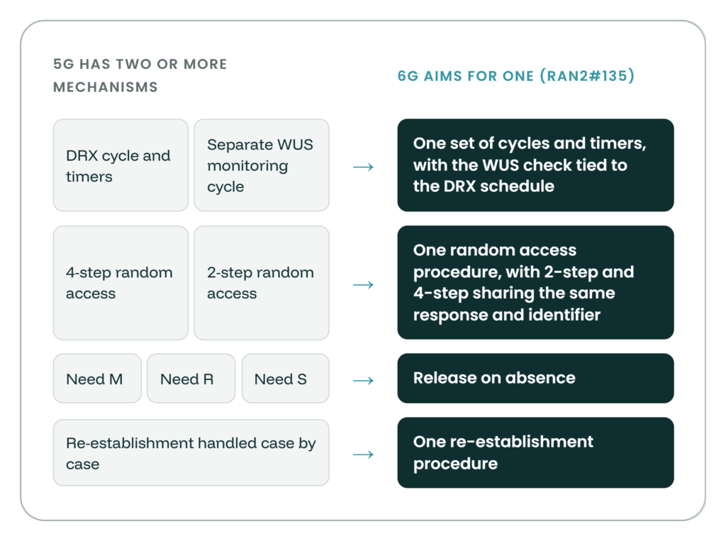
Figure 2. Four areas where RAN2#135 agreed to aim for one 6G mechanism or configuration where 5G has several.
SA2 consolidates two dozen core proposals into three architecture options and keeps the 5G interworking path open
SA2 designs the core network, which authenticates a device, tracks it, sets up its data sessions and applies operator policy. It runs its 6G study as a list of Key Issues, each with several candidate solutions, and Prague had two jobs. The first was to update those solutions, including the details parked as Editor’s Notes at the previous meeting. The second was to open, for the first time, the discussion on the overall architecture and on interim conclusions. Nothing was concluded, and what was established is the starting point for a discussion that continues through the rest of Release 20. Updates to solutions for mobility between 6G and 5G, and for interworking between the 4G core and 6G, were approved. The same keep-or-replace split appears in network slicing, where one approach makes the device unaware of slices and another keeps the 5G slice structure.
Three candidate architecture options and the xAMF placeholder
In 5G, signaling between a device and the core, the Non-Access Stratum (NAS), is carried over a connection that terminates at the Access and Mobility Management Function (AMF), which relays session management signaling to the Session Management Function (SMF) and also registers the device and tracks where it is. That makes the AMF both the core’s front door and its mobility brain, and whether it carries into 6G is the keep-or-replace question with the widest consequences. In June, SA2 had provisionally agreed principles for separating the routing of NAS signaling from access and mobility management, and was weighing whether to evolve the 5G AMF or define a new one. On top of that sits a newer question of where artificial intelligence (AI) functions live in the core, whether in a separate domain that takes intents, requests that state a desired outcome rather than a configuration, or inside ordinary network functions. Until Prague, companies had brought their architecture views one by one. About two dozen proposals were merged into one consolidated summary with three candidate architecture options differing in how AI is supported in the 6G system. The first places an optional AI domain beside the connectivity domain, the second has AI functionality served by 6G network functions, and the third organizes the architecture around AI agents. The summary was noted rather than agreed, so it is a starting point, not a decision. For mobility management it uses a deliberately open name, the placeholder xAMF, covering an enhanced 5G AMF, a new 6G AMF, or routing of NAS signaling through a dedicated Signalling Routing Function (SRF), so that the options can be discussed in one frame. Whether a separate AI domain is needed and whether the design should be AI-native remain open. These are the decisions with the widest reach. NAS design, interworking with 5G and 4G, roaming, and the handling of network and device AI agents all depend on them, with Key Issues 1, 17, 18 and 19 expected to be affected most.
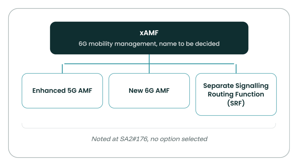
Figure 3. The xAMF placeholder used at SA2#176 lets the three candidate forms of 6G mobility management, which are separate from the three architecture options, be discussed in a common frame.
What’s Next
- RAN1. RAN1#126bis in Jeju in October and RAN1#127 in Calgary in November are expected to down-select the maximum number of layers, the codeword mapping and the DMRS overhead reduction approach. Jeju is also expected to narrow the options for reducing the uplink peak-to-average power ratio, while the number of symbols in the 6G SSB follows the joint RAN1 and RAN4 time plan.
- RAN2. The single sequence number decision returns in October, and the cross-site aggregation study [FS1.1][CL1.2]continues, now covering the multi-vendor deployment scenario the plenary directed be studied.
- SA2. At SA2#177 in Prague in October, the xAMF and AI domain questions will shape the interim conclusions across many Key Issues.